Toyota Corolla (E120) 2002–2008 Repair Manual / Diagnostics / Sfi system / Starter relay circuit high / Inspection procedure
Toyota Corolla (E120): Inspection procedure
Hint
:
- this dtc chart is on the premise that the engine is cranked normally. If the engine is not cranked, proceed to the problem symptoms table on page 05–42.
- Read freeze frame data using the hand-held tester or the obd ii scan tool. Freeze frame data records the engine conditions when a malfunction is detected. When troubleshooting, it is useful for determining whether the vehicle was running or stopped, the engine was warmed up or not, the air–fuel ratio was lean or rich, etc. At the time of the malfunction.
Hand–held tester
1 Read value of hand–held tester(starter signal)
- Connect the hand–held tester or obd ii scan tool to the dlc3.
- turn the ignition switch on and push the hand–held tester main switch on.
- select the item ”diagnosis / enhanced obd ii / data list / all / starter sig” and read the value displayed the hand–held tester.
Result:


2 Inspect park/neutral position switch or clutch start switch

- Inspect the park/neutral position switch. (A/t)
- disconnect the a2 park/neutral position switch connector.
- Check for continuity between each terminal shown below when the shift lever is moved to each range.
Standard:


- Reconnect the park/neutral position switch connector.
- inspect the clutch start switch. (M/t)
- disconnect the c8 clutch start switch connector.
- Check for continuity between terminals when the switch on and off.
Standard:

- Reconnect the clutch start switch connector.


3 Read value of hand–held tester(starter signal)
- Connect the hand–held tester to or obd ii scan tool the dlc3.
- turn the ignition switch on and push the hand–held tester main switch on.
- select the item ”diagnosis / enhanced obd ii / data list / all / starter sig” and read its value displayed the hand–held tester.
Result:


4 Inspect ignition or starter switch assy

- Check for continuity between the connector terminals shown in the chart below


5 Read value of hand–held tester(starter signal)
- Connect the hand–held tester or obd ii scan tool to the dlc3.
- turn the ignition switch on and push the hand–held tester main switch on.
- select the item ”diagnosis / enhanced obd ii / data list / all / starter sig” and read its value displayed the hand–held tester.
Result:


Repair or replace harness and connector
Obd ii scan tool (excluding hand–held tester):
1 Inspect ecm

- Turn the ignition switch on.
- measure the voltage between the terminals of the e4 ecm connector.
Standard:
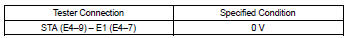
- Measure the voltage between the terminals of the e4 ecm connector when the engine is cranked.
- Standard:


2 Inspect park/neutral position switch or clutch start switch

- Inspect the park/neutral position switch. (A/t)
- disconnect the a2 park/neutral position switch connector.
- Check for continuity between each terminal shown below when the shift lever is moved to each range.
Standard:

- Reconnect the park/neutral position switch connector.
- inspect the clutch start switch. (M/t)
- disconnect the c8 clutch start switch connector.
- Check for continuity between terminals when the switch on and off.
Standard:


- Reconnect the clutch start switch connector.


3 Inspect ecm

- Turn the ignition switch on.
- measure the voltage between the terminals of the e4 ecm connector.
Standard:

- Measure the voltage between the terminals of the e4 ecm connector when the engine is cranked.
Standard:


4 Inspect ignition or starter switch assy

- Disconnect the i10 ignition switch connector.
- check for continuity between the connector terminals shown in the chart below.

- Reconnect the ignition switch connector.


5 Inspect ecm

- Turn the ignition switch on.
- measure the voltage between the terminals of the e4 ecm connector.
Standard:

- Measure the voltage between the terminals of the e4 ecm connector when the engine is cranked.
Standard:


Repair or replace harness or connector


Other materials:
On–vehicle inspection
Notice:
”cold” and ”hot” in these sentences express the temperature of the coils
themselves. ”Cold” is from
–10 c (14 f) to 50 c (122 f) and ”hot” is from 50 c (122 f) to 100 c (212 f).
1. Inspect ignition coil (with igniter) and spark test
confirm dtc.
Notice:
...
Canceling and resuming the constant speed control
1 Pulling the lever toward you cancels the constant speed control.
The speed setting is also canceled when the brakes are applied or the clutch
pedal (manual transmission) is depressed.
2 Pushing the lever up resumes the constant speed control.
Resuming is available when the vehicle speed is mo ...
On–vehicle inspection
1. Inspect for electrical door lock operation
Hint:
w/ power window:
the door control switch is built in the master switch in the driver’s door
and also in the passenger’s
door.
W/o power window:
the door control switch is in the driver’s door and also in the passenger’s
d ...