Toyota Corolla (E120): Inspection
1. Headlamp dimmer switch assy

- Inspect light control switch continuity.
- Measure the resistance according to the value(s) in the table below.
Standard:

- Inspect headlight dimmer switch continuity.
- Measure the resistance according to the value(s) in the table below.
Standard:

Hint
: turn light control switch to the head position when checking ”low beam” and ”hi beam”.
- inspect turn signal switch continuity.
- Measure the resistance according to the value(s) in the table below.
Standard:

- W/ fog light: inspect front fog light switch continuity.
- Measure the resistance according to the value(s) in the table below.
Standard:

2. Back up lamp switch assy
- measure the resistance according to the value(s) in the table below.
Standard:

3. Stop lamp switch assy (w/o cruise control)
- measure the resistance according to the value(s) in the table below.
Standard:

4. Stop lamp switch assy (w/ cruise control)

- Measure the resistance according to the value(s) in the table below.
Standard:

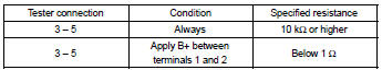
5. Hazard warning signal switch assy

- Measure the resistance according to the value(s) in the table below.
Standard:

- Inspect illumination operation.
- Connect the positive (+) lead from the battery to terminal 5 and the negative (–) lead to terminal 4, then check that the illumination comes on.
6. Front door courtesy lamp switch assy
- measure the resistance according to the value(s) in the table below.
Standard:

7. Rear door courtesy lamp switch assy
- measure the resistance according to the value(s) in the table below.
Standard:

8. Luggage compartment room courtesy lamp switch assy
- measure the resistance according to the value(s) in the table below.
Standard:

9. Map lamp assy (w/o sliding roof)

- Measure the resistance according to the value(s) in the table below.
Standard:

- Connect the positive (+) lead from the battery to terminal 1 and the negative (–) lead to terminal 6, then check that the illumination comes on when switch operation is on position.
10. Map lamp assy (w/ sliding roof)

- Measure the resistance according to the value(s) in the table below.
Standard:

- Connect the positive (+) lead from the battery to terminal 1 and the negative (–) lead to terminal 3, then check that the illumination comes on when switch operation is on position.
11. Room lamp assy no.1

- Connect the positive (+) lead from the battery to terminal 1 and the negative (–) lead to terminal 2, then check that the illumination comes on .
13. Headlamp relay

- Measure the resistance according to the value(s) in the table below.
Standard:

14. Fog lamp relay

- Measure the resistance according to the value(s) in the table below.
Standard:
15. Taillamp relay

- Measure the resistance according to the value(s) in the table below.
Standard:

16. Headlamp dimmer relay

- Measure the resistance according to the value(s) in the table below.
Standard:

17. Light control rheostat

- Connect the connector to the rheostat and inspect the wire harness side connector from the back side as shown in the table below.
Standard:

- Inspect illumination operation.
- Connect the positive (+) lead from the battery to terminal 2 and the negative (–) lead to terminal 3, then check that the illumination comes on.


Other materials:
Overhaul
1. Remove manual transmission filler plug
Remove the manual transmission filler plug and gasket
from the manual transmission case.
2. Remove drain (mtm) plug sub–assy
Remove the drain (mtm) plug sub–assy and gasket from
the manual transmission case.
3. Remove speedomete ...
Front suspension
Service data
*1: Ground clearance of front wheel center
*2: ground clearance of lower suspension arm front bolt center
*3: ground clearance of axle beam set bolt center
*4: ground clearance of rear wheel center
Torque specification
...
Data list/active test
1. Data list
Hint:
according to the data list displayed by the obd ii scan tool or hand–held
tester, you can read the value
of the switch, sensor, actuator and so on without parts removal. Reading the
data list as the first step of
troubleshooting is one method to shorten labor time.
W ...