Toyota Corolla (E120): Inspection
1. Headlamp dimmer switch assy

- Inspect light control switch continuity.
- Measure the resistance according to the value(s) in the table below.
Standard:

- Inspect headlight dimmer switch continuity.
- Measure the resistance according to the value(s) in the table below.
Standard:

Hint
: turn light control switch to the head position when checking ”low beam” and ”hi beam”.
- inspect turn signal switch continuity.
- Measure the resistance according to the value(s) in the table below.
Standard:

- W/ fog light: inspect front fog light switch continuity.
- Measure the resistance according to the value(s) in the table below.
Standard:

2. Back up lamp switch assy
- measure the resistance according to the value(s) in the table below.
Standard:

3. Stop lamp switch assy (w/o cruise control)
- measure the resistance according to the value(s) in the table below.
Standard:

4. Stop lamp switch assy (w/ cruise control)

- Measure the resistance according to the value(s) in the table below.
Standard:

5. Hazard warning signal switch assy

- Measure the resistance according to the value(s) in the table below.
Standard:

- Inspect illumination operation.
- Connect the positive (+) lead from the battery to terminal 5 and the negative (–) lead to terminal 4, then check that the illumination comes on.
6. Front door courtesy lamp switch assy
- measure the resistance according to the value(s) in the table below.
Standard:

7. Rear door courtesy lamp switch assy
- measure the resistance according to the value(s) in the table below.
Standard:

8. Luggage compartment room courtesy lamp switch assy
- measure the resistance according to the value(s) in the table below.
Standard:

9. Map lamp assy (w/o sliding roof)

- Measure the resistance according to the value(s) in the table below.
Standard:

- Connect the positive (+) lead from the battery to terminal 1 and the negative (–) lead to terminal 6, then check that the illumination comes on when switch operation is on position.
10. Map lamp assy (w/ sliding roof)

- Measure the resistance according to the value(s) in the table below.
Standard:

- Connect the positive (+) lead from the battery to terminal 1 and the negative (–) lead to terminal 3, then check that the illumination comes on when switch operation is on position.
11. Room lamp assy no.1

- Connect the positive (+) lead from the battery to terminal 1 and the negative (–) lead to terminal 2, then check that the illumination comes on .
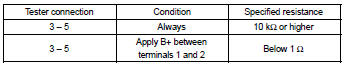
13. Headlamp relay

- Measure the resistance according to the value(s) in the table below.
Standard:

14. Fog lamp relay

- Measure the resistance according to the value(s) in the table below.
Standard:
15. Taillamp relay

- Measure the resistance according to the value(s) in the table below.
Standard:

16. Headlamp dimmer relay

- Measure the resistance according to the value(s) in the table below.
Standard:

17. Light control rheostat

- Connect the connector to the rheostat and inspect the wire harness side connector from the back side as shown in the table below.
Standard:

- Inspect illumination operation.
- Connect the positive (+) lead from the battery to terminal 2 and the negative (–) lead to terminal 3, then check that the illumination comes on.


Other materials:
Speedometer sensor (atm)
Replacement
1. Remove air cleaner case
2. Remove air cleaner hose no.1
3. Remove speedometer sensor
disconnect the connector.
remove the bolt and speedometer sensor assembly.
remove the clip and driven gear from the speedometer
sensor.
4. Install speedometer sensor
...
Sound quality is bad in all modes (volume is too low)
Wiring diagram
Inspection procedure
1 Adjust sound quality
Adjust the sound quality.
Operate the radio receiver assy to adjust the sound quality.
Standard: malfunction disappear.
2 Compare it with another car of same model
Compare it with another vehicle of the same mo ...
On–vehicle inspection
1. Check battery electrolyte level
Check the electrolyte quantity of each cell (maintenance–free battery).
If under the lower level, replace the battery (or add distilled
water if possible) and check the charging
system.
check the electrolyte quantity of each cell ...